1) Generalities and general functions of image manipulation.
Links to position yourself on the right Chapter:
In order to be able to manipulate and visualize comfortably hundreds of images --.TIF of several hundreds of mega bytes each under Autocad, PMS3D has developed display drivers based on standard Autodesk tools (See ATIL Drivers).
These features are only active on Tiled and Pyramid TIF Images (PMS3D Base Files). JPEG compression is an option that allows to reduce the size of the files but makes partial modification impossible. As a result, the image merge function applied to compressed files requires a complete recalculation of the TIF file and is therefore slower.
When loading an image, the PMS3D module creates :
- PMS images if the TIF files are tiled and pyramided.
- Standard images in all other cases.
It is important to know that, in addition to the speed and image quantity capabilities, the "PMS_Images" have color correction features adapted to our orthophoto problems.
All these color compensation settings are stored in the DWG.
For DWG deliveries to third parties who do not have PMS3D software, you can convert these images to Autocad standard.
Conversely, you can convert standard images into PMS3D images:
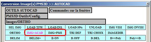
Or by the general menu below or by the command: "PMS_CONVIMG".
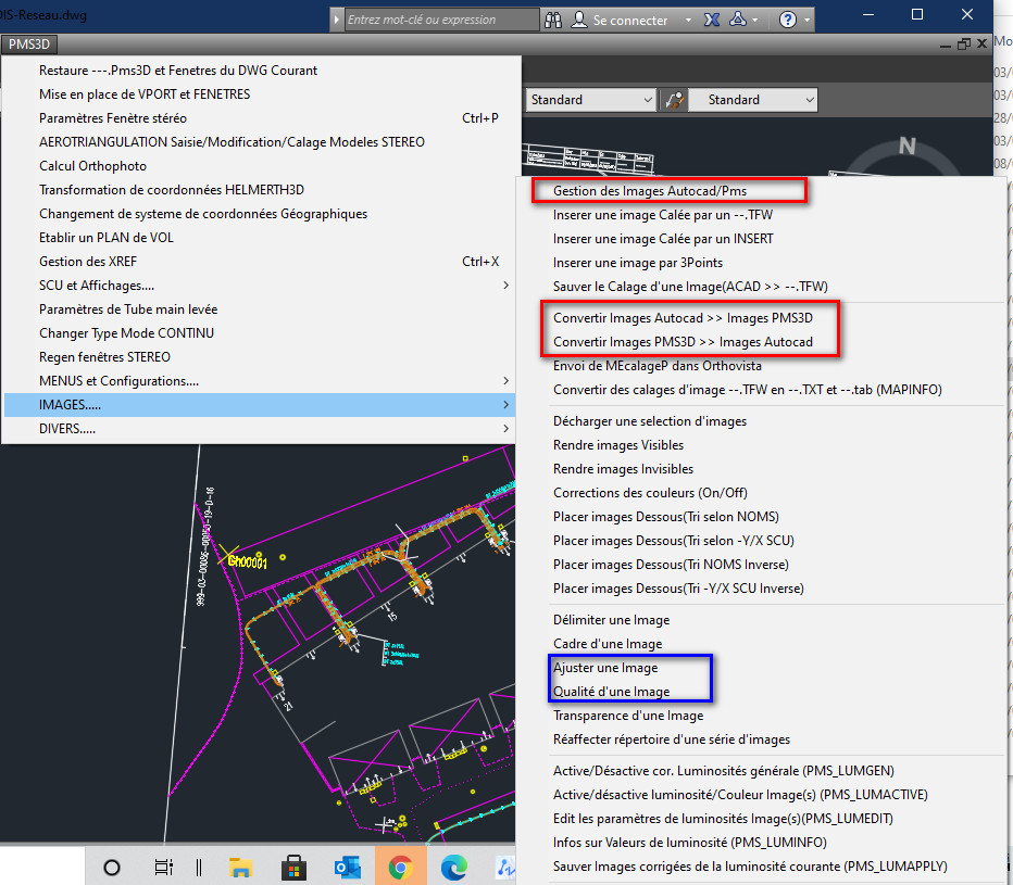
In the menu above a whole series of useful functions for importing, exporting and displaying images have been grouped together.
Some of them are Autocad commands, others are not or do not react exactly the same way.
In particular the image quality in draft mode, when it is a PMS3D image it reverses the overwriting of the Images while in AUTOCAD mode it decreases the quality. In PMS3D mode this feature improves the display speed because it does not overwrite on a pixel already drawn.
In the same way, in Adjust Image, the variable 'Blur ' is replaced by 'Transparency' when it is a PMS3D image.
This notion of transparency is sometimes useful when images are superimposed. It is not applicable when printing (PLOT).
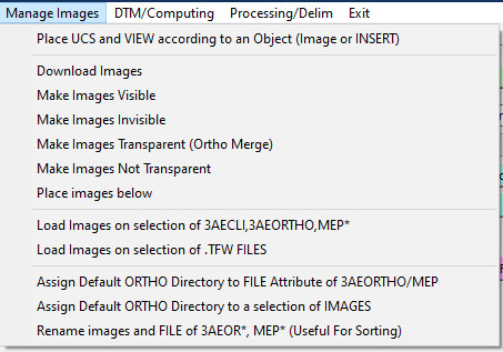
Most of the functions are also found in this menu:
) To change the UCS and make it conform to a selected Object or Image.
) To manage the visibility of an Image.
) To manage the transparency of an Image. This function is important because it allows to make visible the image from below, where above the ortho was hidden. In the case of terrestrial ortho, makes appear zones masked by poles, chimneys or doghouses
Regen by placing the Ortho images under the vectors.
) Loading images by selecting INSERT or files.
) Change directory of image files or 'FILE' attribute of image 'INSERT'. Do not forget to update the default directory of the images
Rename Images in order to place them at the good level (case of sorting according to the names of images).
2) Input and output data.
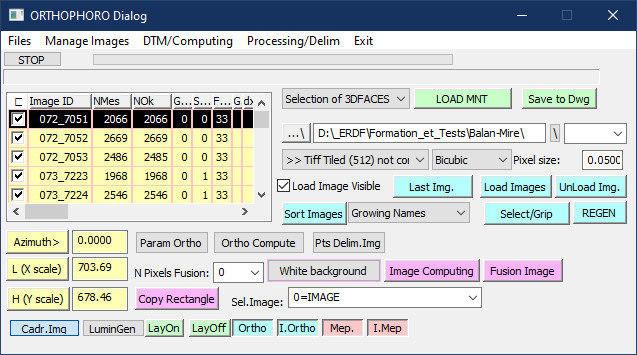
3)Launching the ORTHO module and general parameters.
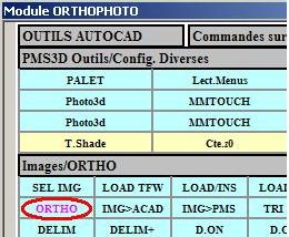
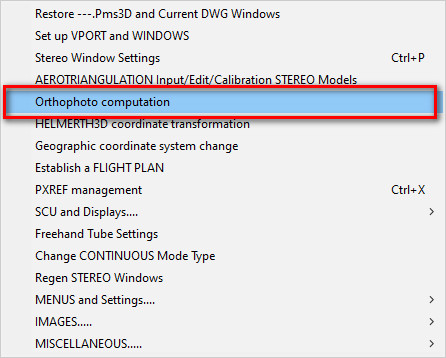
You start this module via the menu or command: PMS_ORTHOor
via the following menus:
The following general parameters will be used by almost all ortho functions.
These parameters are stored in the same file as the Aerotriangulation: Chantier. Model.
) Defines the DTM integration method.
) Defines the directory in which the new ORTHO Images will be stored.
) Prototype the Name of the new ortho images. Leave blank to take the default names. As the order in which the images are displayed generally depends on the Names, it is sometimes interesting to impose them with this Option. The "Manage Image-Rename" menu function can also be used to change the display order
Defines the type of image to create. For Ortho and intermediate images, the Tiled and Uncompressed version is the most effective.
) Sets the pixel size of the Final Ortho. It is not recommended to change this value during processing; mixing images with different pixel sizes results in a loss of Quality. All Insert or Image calculation and positioning is linked to a grid passing through the 0,0 point and linked to this size.
) allows you to filter the selectable images. This is useful when you have overlapping images. See the "SELECT" command in Autocad.
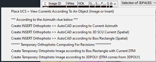
4)Creation/definition of Ortho to be calculated.
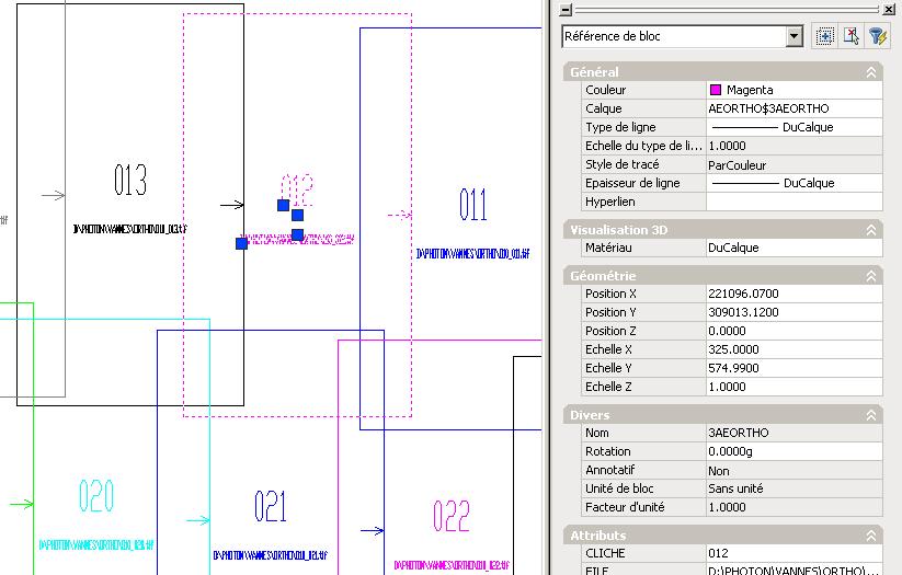
The definition of the parameters relating to the orthos to be calculated is done by creating an INSERT named "3AEOTHO".
Its position and size define the position and size of the image to be calculated.
Its attributes :
CLICK >> Link of this No with the image No of the Aerotriangulation file ---.model. It contains the original image and its orientation elements.
FILE: >> Name of the RECTIFIED ORTHO file that will be created by calculation.
MNTFILE >> Name of the DTM file (DWG faces file) to be used for the calculation (see chapter DTM for the association).
Be sure to check the Parameters for creating these inserts and ):
) Fixes the bearing and scales of the inserts you will create.
After creation, you can readjust the created inserts by Autocad commands or by changing the properties of these INSERT.
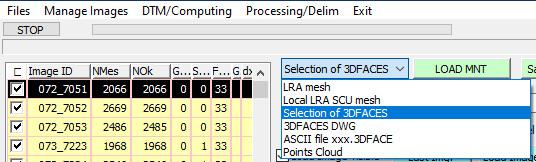
You create these INSERTs by right-clicking on the list of images you need to select:
Values
Is interesting in the case of vertical ORTHO. Case of aerial images.
An insert is created for each selected image. The values relative to () are used
Creates a frame using the position of the selected images. It creates these frames according to the current UCS. Used in the case of Land Photos.
) Creates a frame in the current UCS by asking you the 2 corners of the window. The associated frame is the current frame (GETCORNER).
Results:
Don't forget to save your work by saving your Current DWG.
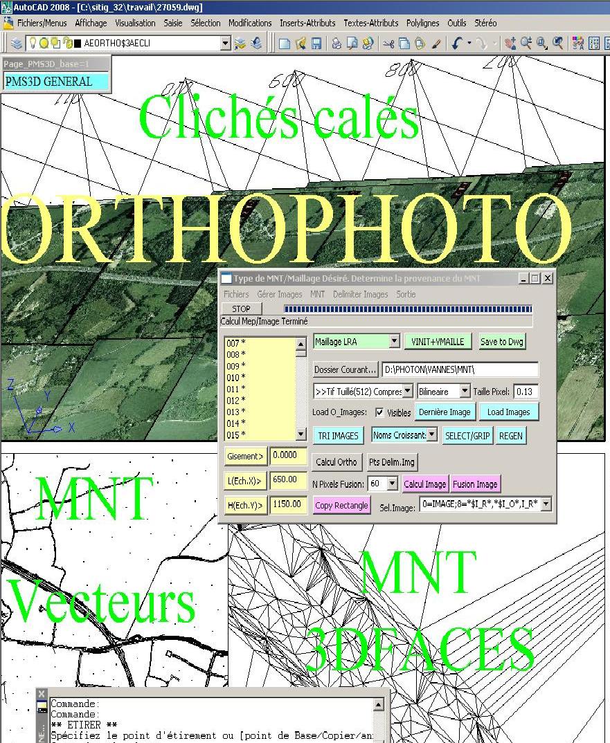
5)Calculation and handling of the DTM.
The PMS3D module requires 3DFACES or POLYMAILLE to ortho rectify the plates.
If you have the "LRA" module or that of another supplier, you will have no problem to mesh and have a terrain model in the form of faces.
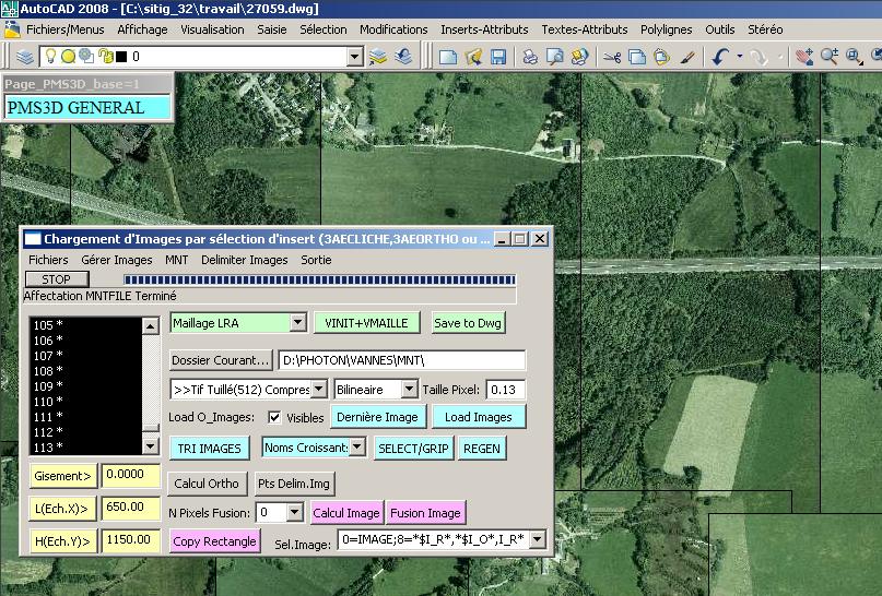
You define the origin of the current DTM by the drop-down list.
) This option requires the 'LRA' software. With [VINIT+VMAIL] you mesh the current DTM which remains in memory as Current DTM for any horto calculation.
) You can integrate the DTM from Autocad objects (3DPoly, PMS3DPOLY, POLYMAILLE).
These objects can come from a selection set or from a DXF or DWG file.
) You can integrate the DTM from an ASCII file. Export some Autocad objects in ASCII to see the Format.
) The software can use a LIDAR point cloud. It exploits the '.LAS' files. You can transform a '.TXT' file into a '.LAS' file using the function in the DTM/CALCULATION menu. Don't forget to set the maximum distance between points of the Cloud (Ortho calculation parameters of the menu below)
You have to load your DTM. Your DTM is ready to use.
) You can save it in a .DWG file.
If you have a large file, you can associate the useful faces of this DTM to each CLICHES to be Ortho rectified.
At your choice, a single DWG file will be associated to several SLIDES or one DWG per SLIDE can be created.
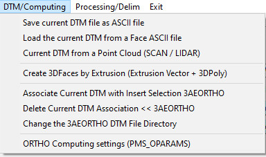
This DTM manipulation is found in the following menus:
You can Export and Import a DTM via ASCII files.
) You can Import a Point Cloud file. If you select an ASCII file, its extension sets the column list of this ASCII file. It is then converted to a '.LAS' file.
) To associate and dissociate DTM files with certain Images.
This allows, when ortho rectifying an image, to work on a more restricted DTM; only the interesting faces of the image are saved.
This is interesting for large files.
) When you have associated DTM files to some Images, you can change the directory.
) Default settings for image calculation and display are defined.
) Small extrusion function to create 3DMAILS from Polylines or closed 3DPOLY. This allows to complete DTM for chimneys or other objects. You must provide an extrusion vector
Don't forget to save your work by saving your Current DWG.
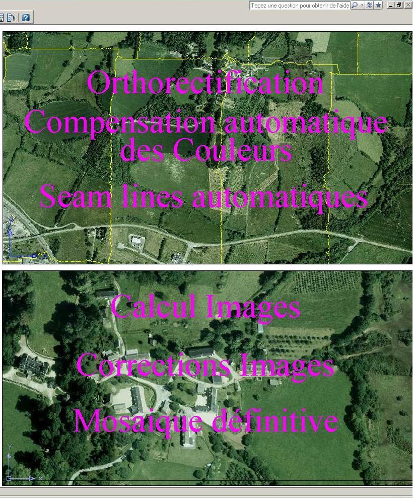
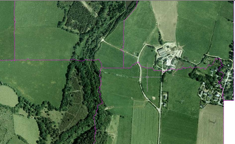
6)Orthorectification of images.
You trigger a calculation with the ORTHO CALCULATION button:
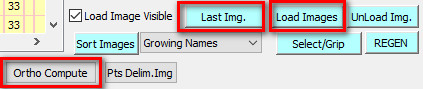
Now that the calculation is complete, you can see the result by loading the images with [Load Images]
You can view and manipulate the RECTIFIED ORTHO images using the Functions:
) To load the last automatically rectified ORTHO image
) To load the last calculated image.
) To load images by selecting the associated INSERTs or to unload them.
Don't forget to save your work with a backup of your Current DWG.
For more comfort, it is interesting to delete all the INSERT 3AEORTHO. You don't need them anymore.
7)Brightness and color correction.
General
If the colours seem to be correct and the changes in the images are not too noticeable, go to the next step.
You can change the luminance and contrast values using the classic Autocad commands.
Grab a whole series of images and change these luminance and contrast properties serially.
Another method is to use the automatic correction of PMS3D according to the least squares.
To do this, you must block the images that are to be used as references (at least the 4 corners of the site).
You just have to force the color of these reference images to 1 (Red).
Start the calculation with the menu "Processing/Delim" of the dialog box "ORTHO" and the following commands, corresponding to three steps:
- The definition of the parameters for the calculation of the
- The least squares calculation of the color compensation settings for each selected
- To edit, Export as ASCII or Import the luminance parameters of selected images
- To list the luminance information of images to be selected
- The least squares calculation of the color compensation settings for each selected
- Saving the new images corrected by the previously calculated compensation.
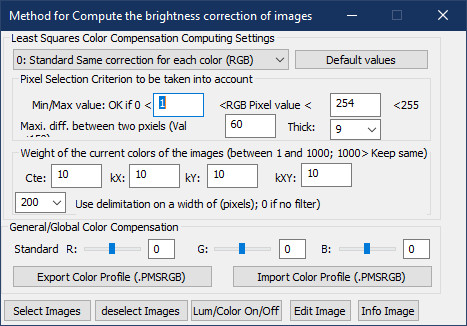
Definition of Luminance calculation parameters (Ortho Def)
- Drop-down list to select the calculation mode:
- Standard mode. The colors have the same coefficients. Only the luminance (lighting) is processed. This is generally what is used.
- Standard mode but with RGB weighting. Green has a much higher weight than blue. This is what is used to make JPEG files.
- Independent color correction. Each color is processed independently and has its own compensation coefficients.
- Only one colour is processed; the others remain unchanged.
- This is to filter the pixels to be included in the compensation calculation. Any color has a value between 0 and 255 (1 byte).
The variables in the current case, allow to consider only the pixels included between 1 and 254. One thus eliminates the pure black and the pure white.
In the case of a calculation by independent color, the filtering is done color by color. In the contrary case, the 3 colors of the point must respect these limits.
The variable corresponds to a limitation of the distance between 2 pixels to be correlated. A value of 60 means that if a pixel of image 1 has a value of 100, the corresponding pixel of image 2 must have a value between 40 and 160 for there to be a correlation
- Drop-down list To specify the fineness of the calculation. 9 means that the image is divided into 9*9=81 pieces. Each piece will correspond to a compensation data.
9 is a value which makes it possible to treat 4000 images without having problems of overflow of memory.
Each color of each image will be compensated by the formula: Color = Start Color + kX * X + kY * Y + kXY * X * Y + Cte;
X and Y varying between -0.5 and 0.5 according to the position of the pixel;
kX, kY, kXY and Cte being coefficients to be calculated. kXY corresponds to a kind of torsion
We consider that we stay as close as possible to the colors of the original images. Otherwise, the best way to avoid seeing any transition between the images would be to put them all in black or white.
The more the original images have weight, and the less we allow the change of colors. This adjustment is done thanks to the coefficients .
It is generally interesting to focus on the color correlation at the image changes, where the boundary lines are.
This is done by the variable , the boundary width to be used (in image pixels). In case this value is not zero, the color compensation must be done after the delimitation of the images.
In all cases, the points taken into account by the correlation are the visible points, and if the image is delimited, only the displayable points are taken into account.
This allows you, for example, to exclude water surfaces from the image or to limit the overlap between bands, to eliminate areas that disturb the color calculations.
Definition of Luminance calculation parameters (Ortho Auto)
This function allows for least squares color compensation calculations.
You have to start by defining images that will be used as reference; images that will remain unchanged.
To do this, you must assign them the color RED
. These images are generally the 4 corners of a block or the ends of the strips. A good compromise is to put about 1 Image out of 10 in red.
You just have to run the calculation on a selection of images.
After seeing the results, you can change the weight of the coefficients, impose other images, delimit disturbing areas and run the calculation again.
Do not forget to save your work by saving your current DWG. The compensation coefficients are stored in the DWG
Save images corrected for the current brightness. (Ortho Save)
This function allows you to modify your original image by correcting it with the current color compensation.
During the whole calculation phase, this is not necessary. It is preferable to work with a real time calculation at the time of the display.
The display is a bit longer but you keep your original images.
This function is interesting for the delivery of the compensated images to the final customer because he does not have this module which compensates at the time of display.
The general color compensation as well as the Autocad brightness and contrast coefficients are also taken into account by this module.
As the images are modified, the compensation coefficients are automatically set to zero.
General color correction.
Before the final delivery, it is sometimes necessary to correct the colors globally. Forcing green or reducing red for example.
You can
adjust in real time the "RGB" colors of all images on which the color correction flag is active
For a more precise adjustment, you can, via an ASCII file "PmsRgb" define a very precise graph of the corrections to be brought.
This import/export to an ASCII file is executed by the buttons : .
The file contains lines of the form:
[R and/or G and/or B]xxx=yyy. whereR
for Red, G for Green, B for Blue.
xxx = value of the color of the pixelyy
= New value for this pixel.
For example:
R128=120 to create a pass point attenuating red from value 128 to 120.
RGB128=120 to create a pass point attenuating all 3 colors from value 128 to 120.
You thus create pass points for each color.
The intermediate points are interpolated.
At the beginning, for each color, 2 points are automatically created, R0=0 and R255=255.
The buttons make it possible to select/deselect the plates concerned by this color correction.
Input tools, manual editing and quick access to color correction functions.
) To enable and disable the color and luminance change flag relative to each image.
The function is called. This function is also in the PMS3D/Images drop-down menu.
) To manually edit or import/export corrections for each selected image.
The corresponding function is . This function is also in the PMS3D/Images drop down menu.
command:PMS_LUMEDIT. It offers 4 Options :
/Change /Reset /Export /Import :
- Click on "Change" to edit the settings for a selection of images. The first image provides default values that you can change.
All the selected images will take these new corrections.
- Reset" to reset the corrections of a selected image
- Export" to export the selected image corrections to an ASCII file
- "Import" to import the corrections previously exported and possibly processed by you.
Each line of the file is of the form:\Fs2\photo6\271012_ORTHO\O10_35_0979
.tif,3,1.08,-0.16,-2.92,-0.31,1.08,-0.16,-2.92,-0.31,1.08,-0.16,-2.92,-0.31The
coefficients for each color are: Cte, kX, kY, kXY that is to say 3*4 = 12 coefficients by image.
launches the command which allows to list the correction coefficients of an image. It can also be found in the PMS3D/Images drop-down menu.
Enables/disables the taking into account of Brightness and Color corrections.
This global variable allows to visualize immediately the display with and without luminosity and color corrections.
In order for the brightness and color corrections to be taken into account on an image, this flag and the image flags must be active
8)Delimitation of the Images.
In the case of simple ortho photos (no built-up area and uniform vegetation), this can be dispensed with.
Otherwise:
) Launches a regeneration of the drawing by respecting the order of display of the images according to the selected criterion (in general Increasing names)
) Allows to choose a criterion of SORT of the images. In general Ascending Names. This sorting is important because only the visible parts of the Images are delimited.
It is useless or even penalizing to delimit the parts covered by other images of higher rank
Starts the automatic delimitation calculation. The current order of the images is taken into account. Red PICTURES are not processed.
This function roughs up the work. Modifications can be made by the functions described below.
) Allows the modification of existing boundaries by adding and deleting points or sections.
A point can be deleted by snapping it in End mode.
) Activate and deactivate the delimitation of one or more Images
Complete deletion of the delimitation of one or more Images
Autocad function of image delimitation
Delimitation from a polyline
You can Export then modify and import these delimitation contours as polylines
 You get something out of the form:
Don't forget to save your work by saving your Current DWG.
9) Definition of the final images to be created.
At this stage you can already make good quality Autocad prints.
Compared to the following treatments, the printout does not include an image fusion calculation (width defined in pixels).
You should start by checking the main settings for image extraction and merging:
- Prepare the current folder for the creation of new Images as well as the Name prototype and ).
- Choose the type of image to create). Uncompressed tiled images are interesting because they have the advantage of being able to be loaded quickly (tiling) and to allow partial modifications (merging). Compressed images do not allow these modifications. Any merging of a compressed image results in the creation of a .bak and the complete rewriting of the file.
- Set the width of the image merge. This merge is applied inside the bounding box. At the edge of the line, the outer image is very strong, the further away you get from this edge, the more weight the image has.
- Allows to have a WHITE background image, where there was no ortho (non-ortho rectified area).
- You can also refine the image selection filter).
As with the creation of orthorectified images, we use INSERTs to create these final images in series.
The name of these INSERTs must begin with MEP (Page Setup). We use "MEP_IMG".
Two functions exist: and another for its duplication in series:
One for the creation of the first Insert "MEP_IMG". It defines the prototyping of the Name and the future MEP_IMGs which will result from it by duplication.
As soon as you insert the first "MEP_IMG" check all these parameters before duplicating it in L rows and C columns:
This Menu calls the command: "PMS_INSERT" which is interesting for the creation of INSERT in spatial mode.
Be careful, the points clings are spatial. Don't forget that PMS3D software is 3D oriented.
Ortho rectification works with 3D rotation matrices.
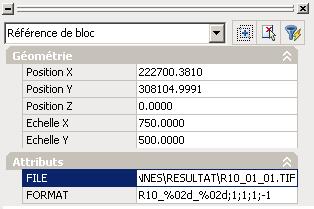
The FORMAT attribute defines how the future images will be named according to their Line/Column position.
In this case, "R10_%02d_%02d;1;1;1;-1" means that the image shifted by 2 lines above and 3 columns to the right will have the name: "R10_02_03
". The '%02d' format the writing of the Numbers. We also have Digit1= 1 + 1 * [N° Col] ; Digit2= 1 - 1 * [N° Line].
This formatting is of the form: FORMAT; CteCol; KCol; CteLigne; KLigne. This first MEP_IMG being checked, you duplicate it so as to cover all your project.
) Starting from a prototype MEP_IMG, this function allows its duplication in 'C' columns (positive to the right) and 'L' lines (positive to the TOP).
The sign of 'C' and 'L' is interpreted and allows to choose the duplication direction.
If the answer to the question "Number of columns" is negative, the duplication will be to the right.
If the answer to the question "Number of rows" is a negative number, the duplication will be downwards.
The duplication function can be run several times.
If you want an overlap of your images, change the X and Y SCALE properties of the INSERT objects (GRIPPER these entities and change the properties).Result:
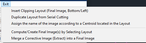
10)Creation of the final images.
To create the final images, or Extracts, the solutions are :
- ) Calculates the Images on a selection set of "MEP_IMG" (See Dialog .
- Calculate the Images on rectangle. The 2 corners of the rectangle are requested.
- The Image Recovery Functions explained in the next chapter (recalculation of partial ortho).
Once the calculation is done, you load these images : [Load Images] on a selection set of "MEP_IMG".
Don't forget to save your work as a .DWG Current.
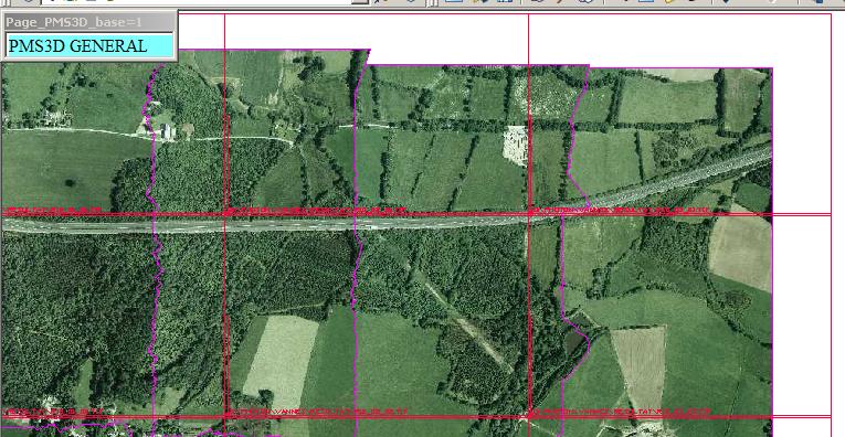
11)Final Image Editing Tools.
To work comfortably, it is interesting to work on at least 2 windows in paper space.
In the first window, the ortho rectified images with their delimitation contours are displayed, and in the other, the final images.
For this purpose, in each window, some 'LAYERs' are frozen.
The concerned layers are "I_O10.." for Ortho images, "MEP_IMG" for MEP images, "I_O10.." for Final images; This way, you will have more ease
when selecting images and you will have a real time view of the result.
We get:
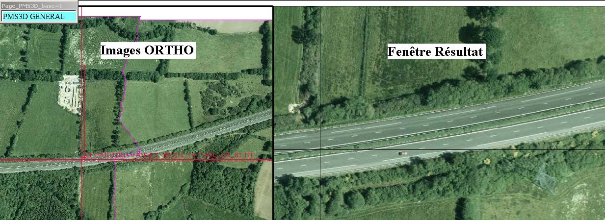
The principle of the changes is as follows:
- Create a transfer image of the field to be changed.
- possibly duplication, moving, rotation, scaling, delimitation
- Merge this image into the Final Images.
Detail:
- Tools for creating a rework image of the area to be modified.
From the initial images and either the current DTM+window or a _3DPOLY (valid in Z).
The 3DPOLY is interesting for the resumption of bridges for example. It serves as a DTM for the calculation and as a boundary polygon for the final image.
) To ortho rectify the selected images by defining a rectangle (GETCORNER). The image is quickly created and if the prototype name is well chosen, this image must cover all the others and be visible. It can then be merged. The current DTM must be up to date.
This function is interesting for the resumption of bridges for example. It is enough to create a closed '3DPOLY' surrounding this bridge to orthorectify this polygon. The DTM is based on this 3DPOLY; the heights must be correct.
- Merging of a cover image into the final images.
) This button allows the merging of images. The base images are modified and saved. The luminance parameters and the current merging distance are taken into account and integrated in the recalculated image. The original images are lost. These modified images can be delivered as is.
12)Tools/Miscellaneous buttons to activate/deactivate the right objects.
) Enables disables IMAGES FRAMES.
) Enables disables the brightness and color correction by the general variable (). This allows you to quickly see the difference in color correction.
) Activates all Autocad layers.
) Deactivates all Autocad layers.
) On/Off of ORTHO INSERT images.
) On/Off of ORTHO images.
) On/Off of MEP final images.
) On/Off of definitive images