General principles A transformation of coordinates makes it possible to pass from a system of coordinates towards anotherIn
this case one passes from a Local system (Graph or measurement), towards a general system (Ground, World)
That makes it possible to place in general system of the Images, files in references (XREF) or simply of the simple entitiesIt
is necessary to provide a series of points in the system of measurement with their corresponding in the general system.
For that, several methods are possible: - The integration of entities Lines and texts.
- The lines provide the 2 positions and possibly the texts impose a name of pointThe
- integration of points in general system (in the same way as for the Aerotriangulation) and the point of each one of them in the local system(s)The
- consecutive point, for each point of their positions in local and general system
- The integration of links resulting from another calculation made with this software PMS3D
A Notion of System is introduced.
This functionality is interesting in the sense that it makes it possible to apply successive transformations of coordinates to entities while preserving the system of departure.
We can thus superimpose the entities of a local system with those of the general system in order to better correlate them and find the transformation starting from the original system.
Block compensation only works in 2D. It allows the integration of transfer points between wedges. A transfer point is a point appearing on several layers and not existing in the general system
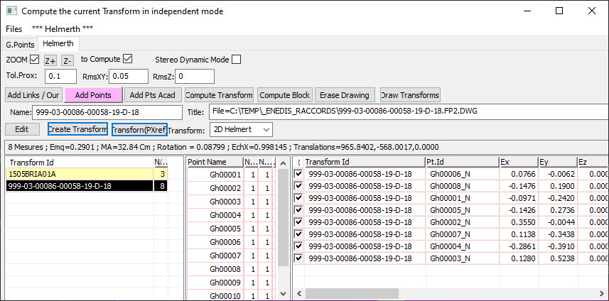
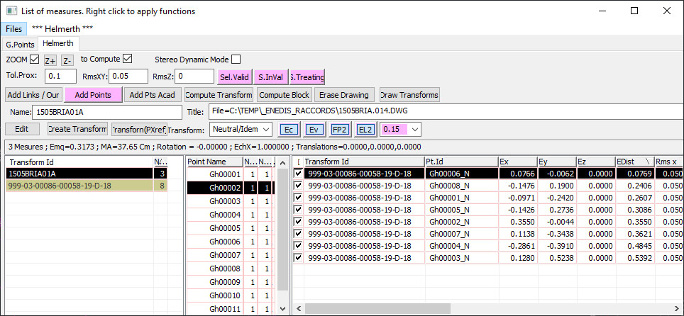
Coordinate transformation (Helmerth 2D/3D)
) Allows an automatic centering of the view on the points when it is interesting
Launches an automatic calculation of the shimming when it is interesting
Root mean square error in XY by default
Root
mean square error in Z by default
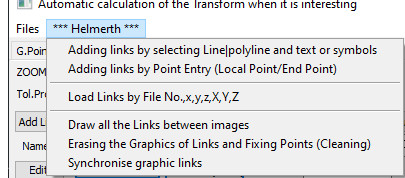
Import of measurements by selection of graphic entities.
Lines (or polylines with exactly 2 points) generate a new data. The first point corresponds to the local system and the second to its corresponding in the general system.
If a text (or an Insert with attribute) exists at one of the ends of this line, this text will Name the point.
If no text exists, an automatic Name of the form "Gh000010" will be automatically created.
) For the direct entry of measurements by successive pointing of the point in local followed by the point in general system
For the calculation of the current setting in Independent
)
For the block calculation of all settings, including those not selected.
3D transformations cannot be processed at this time.
) Input of the current layer name. Used when creating a new layer or renaming the current layer.
Enter the current Layer Title. Used when creating a new cushion or renaming the current cushion.
) To rename the current layer.
) To create a New Layer.
) To assign a type of calculation to the current layer:- 2D Helmerth: Classic Helmerth transformation.
- Scale, translations and Rotation2D
- Rectangle: Scale in X, Scale in Y, translations and Rotation2D
- Affine: Scale, translations and Rotation in X; Scale, translations and Rotation in Y2D
- Rot+Trans: Translations and Rotation
.- No scale2D
- Translations: translations in X and X3D
- Helmerth: Helmerth transformation in classical 3D.
- Scale, translations and rotations3D
- Rot+Trans: Translations and rotations.
- No scale3D
- Translations: Translations in X,Y,Z
( General information about the Current setting
Helmerth" general menu
Same function as (HD_06)
Same function as (HD_07)
To import a formatted data file "Name x y z X Y Z". The separator being a ' '(space)
To draw all the links of all the layers. A link is composed of a line and an Insert '1AEPTCAL' placed in the Layer :'HLINKCAL'
These elements have an XDATA 'HCALNAME=NomCalage;NomPoint'. This XDATA allows the maintenance of the synchronization
To delete all the links generated by the previous function
To synchronize all the links generated by the previous function. The XDATA 'HCALNAME=NameCalage;NamePoint' allows this synchronization.
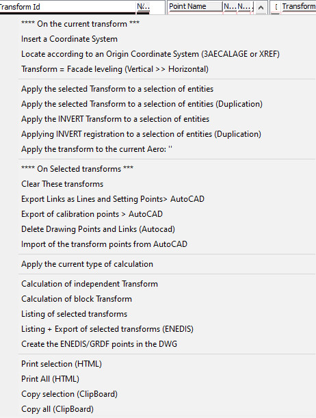
Helmerth menu related to wedges
To insert a coordinate system. In reality, we insert an INSERT: '3AECALAGE' at the origin of the Local system.
The best is to insert it before any transformations to coordinates 0,0,0 without rotations.
If you work with an XREF, the XREF itself plays the role of this system of
co-ordinatesThereafter, it will be necessary to apply the same transformations to this system as to the entities which are attached to itThus
, it will be possible for you to transform the modified setting by a series of transformations into a setting making it possible to pass from this original system to the transformed systemIn
practice, the following handling is carried out:- this system is placed in its original coordinates,
- 2 or 3 measurements are entered, and the entities related to this setting are transformed
(Be careful to use only conforming transformations; exclude Affine or Double Scale transformations) .-
Thus, one puts in superposition the entities of the local system with those of the general systemOne - can also move in an interactive way the data of the original system by using the AutoCAD commands: MOVE , ROTATE and SCALE , without forgetting to put the Block 3AECALAGE in the selection set
.- It is also interesting to have a slight offset between the 2 systems to facilitate the taking of measurements.
- we complete the measurements until we obtain the final transformation
.- We can transform the entities and list a result showing the calculation differences. These differences do not take into account all the intermediate transformations that have already been made
- We relocate in the original system (next function) in order to relocate the system in 0,0,0 origin of the initial settingThe
- transformation and its measurements are then similar to what we would have obtained if we had not moved the entities to put them in superposition
( To return to the original system. See explanation above
To apply this transformation to a selection set by displacement. Include the Original system and put the current set in conformity if necessary.
) To apply this transformation to a selection set by copy. The original entities are kept.
) To apply this transformation in reverse to a selection set by copy.
) To delete the selected layers.
) Same function as (HD_04) but on a layer selection.
) Same function as (HD_05) but on a cushion selection.
) To import measurements from the INSERT '1AEPTCAL' chart items to be selected.
) Apply the current calculation type listed in to the (HD_15) selected wedges. See explanation above
)
To calculate the selected layers in independent mode.
) To calculate the selected layers in Block.
) To generate a calibration report.
Points menu (right click)
) To enter a change of data starting from the Point Name as an element.
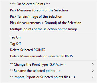
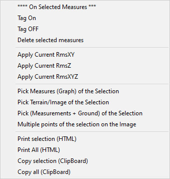
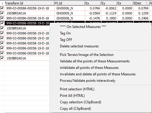
Measures menu (right click)
) To activate/deactivate or delete measurements.
) To modify the Emq for these measurements. Set the correct default value in the dialog box.
) To modify the selected measurements in chain.
Translations [Rotations] of Entities (PMS_EMOVE)
This function allows to move in translation [rotation] a selection of entities.
Interesting to move a street body when you know a point in both systems and possibly a direction.
For linear entities, it is possible to limit the displacement to the points located in the polygon of capture of the selectionFunctions
like the command "STRETCH" of Autocad.
When Point is requested, the 'P' option allows to define the parameters of this function.
The parameters are :
- P : to test that the points (polylines only) are in the selection polygon.
If no polygon to select the entities (of type Capture or Window), then ask for a polygon
- T : to test that the points (All Points, including symbols and texts) are in the selection polygon.
If no polygon to select entities (of type Capture or Window), then ask for a polygon
- Z: To allow also the movement in Z of each object.
- D: A Dynamic mode cue (Only if cueing on Photos in an existing Stereoscopic View).
- B: Dynamic loop mode. The request for a translation point and then a rotation point is requested until validated by an [ENTER].
- V: Processes only entities that are Visible.
- C: Automatically starts the selection of the entities to be moved by the mode '_CP' = Capture polygon.
Enedis, Géoref Massif (HELMERTH3D)
Functionalities developed specifically for ENEDIS in order to control the 'GEOREF MASSIF
'The input files come from a treatment made under microstation and have for Extension '.GEOREF'
The simple fact of loading in HELMERTH one of these files, switches the module HELMERTH of PMS3D in MODULE of georef control.
This module facilitates the loading/unloading of ENEDIS folios (in DWG or DGN
). It allows the validation of control points by Helmerth menu or by Autocad selection
) Allows to enter new control points, where there is a lack of points.
To highlight the places where these points are needed, change the size of the control points (HG_04).
Toggles to make visible or invisible the control points and the validated points.
This function works both on the lists and on the Autocad drawing.
) Toggles to make the Electricity and Background layers visible. This function acts on the Autocad drawing.
) To change the size of the point drawing on Autocad. Initially, this function takes the value of the tolerance of the ".GEOREF" file.
Toggles to make the Electricity and Background layers visible. This function acts on the Autocad drawing.
) To validate a selection of points graphically (see below)
)
To de-validate a selection of points graphically (the de-validated points return to the control point).
) To interactively validate a selection of control points.
) List of sheets in the .GEOREF file.
) List of points in the .GEOREF file.
) Table of measurements for the selected sheet(s).
It contains the columns of differences between the Graphic Control points and the Terrain points or points from the stereoscopic points.
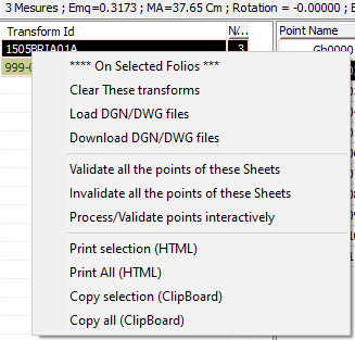
Georef menu related to Folios or Measures (right click)
) To validate all the points relative to the folios or measures selected in the list.
) To disable all the points relative to the folios or measures selected in the list. The deactivated points return to the control point.
) To validate in an interactive way the points relating to the folios or the measures selected in the list.
Options for handling Points in Interactive mode
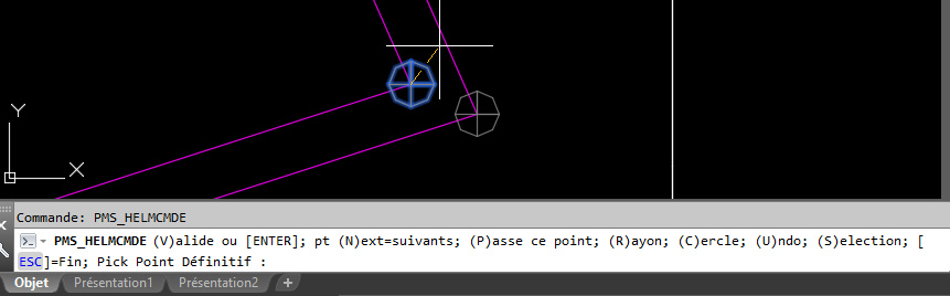
Interactively, you have the following options:
- Enter] or 'V': To change a control point to a validated point within tolerance. The size of the point is equal to the accepted tolerance.
The validation acts on the current selection or on the points located in the current action circle.
- Pick of a Point]: To validate a Field Point (Stereoscopic) associated with the Graphical Point=Current Control Points. The current point is thus validated, but with a deviation from the defined terrain point.
The and the deviation from the Terrain point is transmitted to the points located in the current action circle.
- 'N': To skip the next control point. Points within the current action circle are also passed.
- P': To move to the next control point. Does not take into account the current action circle.
- R': To change the current action circle. By changing this radius, we will consider that the points located in this current radius will follow the same treatment as the current point.
- C': We create a circle of reference to come back to it more trad. We go to the next point, the action circle is taken into account.
- U': Undo. We go back to the previous action.
- S': Instead of using the action circle, for this point we will use an Autocad selection set which you will be asked to do.